Journal club: Shi et al, 2016
Real-time in vitro intravascular reconstruction and navigation for endovascular aortic stent grafting
Chaoyang Shi | Carlos Tercero | Xianliang Wu | Seiichi Ikeda | Kimihiro Komori | Kiyohito Yamamoto | Fumihito Arai | Toshio Fukuda
Int J Med Robotics Comput Assist Surg 2016; 12:648-657
DOI: https://doi.org/10.1002/rcs.1736
This paper is introduced as a new framework for three-dimensional (3D) intravascular reconstruction. The method relies on the information obtained from intravascular ultrasound (IVUS) imaging and electromagnetic (EM) tracking. Moreover, two main working steps are described, a segmentation algorithm for lumen contour in IVUS images and, in order to achieve a 3D reconstruction, the fusion of the determined segmentation data with tracking data.
When treating intravascular diseases, regardless of the chosen procedure, several challenges emerge. If considering imaging techniques for instance, angiography is widely used to obtain several 2D images in order to acquire intraoperative visual information. Alongside, IVUS imaging can also be used as a different approach, capable of providing real-time two-dimensional (2D) precise morphology of various intravascular conditions. Both the aforementioned modalities occur with the limitation of only providing 2D views, which most often leave the relative 3D information to be determined by the surgeon. Shi et al. point out the fact that IVUS imaging has shown great potential when it comes to support the development of 3D volumetric visualization techniques, and consequently, the increase of research concerning the use of IVUS for 3D reconstruction. Additionally, the authors state that research published prior to their paper “cannot apply for intra-operative guidance in real time due to the heavy computations”, backing up alongside the need for “an efficient technique for 3D intravascular visualization”.
Generally, the proposed framework (Figure 1) is made up by an integrated probe of an IVUS catheter (Volcano Visions PV 8.2, Volcano Corporation, USA) and a 6DOF EM sensor (NDI Corporation, Canada), an IVUS imaging system (Volcano s5TM, Volcano Corporation, USA), an Aurora electromagnetic tracking system (NDI Corporation, Canada) and a 3D printed phantom of an ascending aorta (built in accordance with CT imaging data).
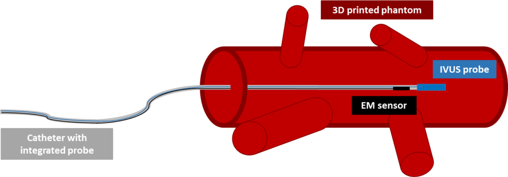
Shi et al.
Concerning the lumen contour extraction/segmentation, the authors enumerate a series of steps which are intended to avoid time-consuming heavy computations and therefore, achieve real-time application. First, a Kalman filter is applied to the EM data to smooth the catheter pose and orientation information. Next, images are converted to greyscale, reducing the number of channels to process and thus, overall processing time. A median filter is used to suppress the noise (which appears due to the high working frequency of the IVUS system, 10 MHz) and the center of the IVUS probe is determined by applying a Hough circle transformation. After, a pre-capture mask image is used to remove unchanged background, while a circular mask removes the IVUS probe and its surroundings in the image (called ROI1 by the authors). Again, a median filter is applied to suppress noise. In order to overcome the difference in intensities appearing from consecutive IVUS frames, an adaptive thresholding method is used to obtain a binary image. Additionally, dilation and erosion techniques are applied to obtain smoother contours and eliminate noise.
Following the aforementioned steps, considered as a pre-processing stage, a radial scan is performed and a random sample consensus (RANSAC) algorithm for ellipse approximation is applied. This is an iterative method which can be broken down into two stages. Firstly, a sample subset is randomly selected from the input dataset, that is determined from the radial scan. The ellipse fitting model and the corresponding model parameters are computed using only the elements of this sample subset. Secondly, the RANSAC algorithm checks which elements of the entire dataset of points are consistent with the model obtained using the data subset. Taking into account a certain threshold, an outlier is determined as an element that does not fit the model. This process is repeated and finally, the best fitting model is selected.
A second radial scan, centered at the center of the calculated ellipse (the best fitting model), is then carried out to remove further outliers. The remaining points are converted to polar coordinates and interpolated by means of B-spline interpolation. The center point of the vessel is then obtained by converting the results of this interpolation back to rectangular coordinates and performing ellipse approximation, taking the center of the ellipse as the center of the vessel. The initial conditions and the last obtained information from the process described above are shown in figure 2.
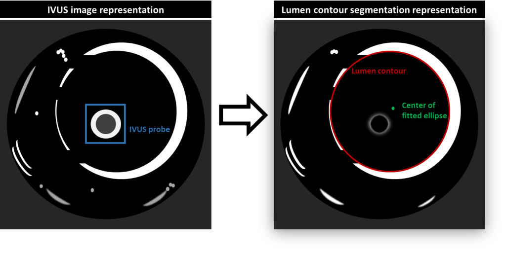
contour with the method of Shi et al.
Finally, 3D reconstruction is said to be achieved due to kinematic transformations and relationships between both the IVUS probe and the EM sensor, and the EM sensor and the Aurora tracking system. This is, coordinates in the 2D IVUS images are transformed into 3D coordinates in a global coordinate system. As the probe is pulled through the phantom, IVUS images and EM tracking data are recorded and used with the proposed framework.
The error reported by the authors between the reconstructed vessel and their ground truth (STL data) regarding the radius difference along respective cross-sections was of 0.64 mm. Furthermore, the error was measured after iterative closest point (ICP) alignment of both structures.
Discussion
Shit et al. assert their method to be stable and fully automatic. In addition, when compared to offline modeling, this method is reported as more efficient, with higher processing speed and presenting better modeling quality. However, it is also said that the contour extraction is susceptible to errors both in the presence of image artifacts and when the IVUS probe is near the vessel wall. In general, this framework is portrayed as allowing for real-time navigation and 3D reconstruction with significant potential for practical applications, consequently improving the efficiency of vascular treatments. The authors statements gave rise to various doubts during discussion in this journal club event. Focus was mainly given to the assumptions made by the authors. The ESR leading the discussion pointed out the fact that the assumption of the lumen contour not changing significantly in sequential IVUS frames to be unrealistic when manually manipulating the catheter. Furthermore, it was not clear for another ESR if there was an assumption of vessel rigidity in the described framework, and how it would deal with the deformability of vascular structures. On the other hand, it became clear as the debate progressed that the method developed for segmentation of the lumen contour is robust and very relevant as it seems to handle several of the drawbacks associated with IVUS imaging. Finally, a note was made regarding both the details given for the image preprocessing methods and the influence of performing ICP alignment if wanting to achieve real-time visualization. Similar to all the steps, more detail on the reasons why some preprocessing methods are needed would also have been beneficial for the full understanding of the working steps. In the same way, a clearer portrayal of the real-time characteristics of the system was missing.